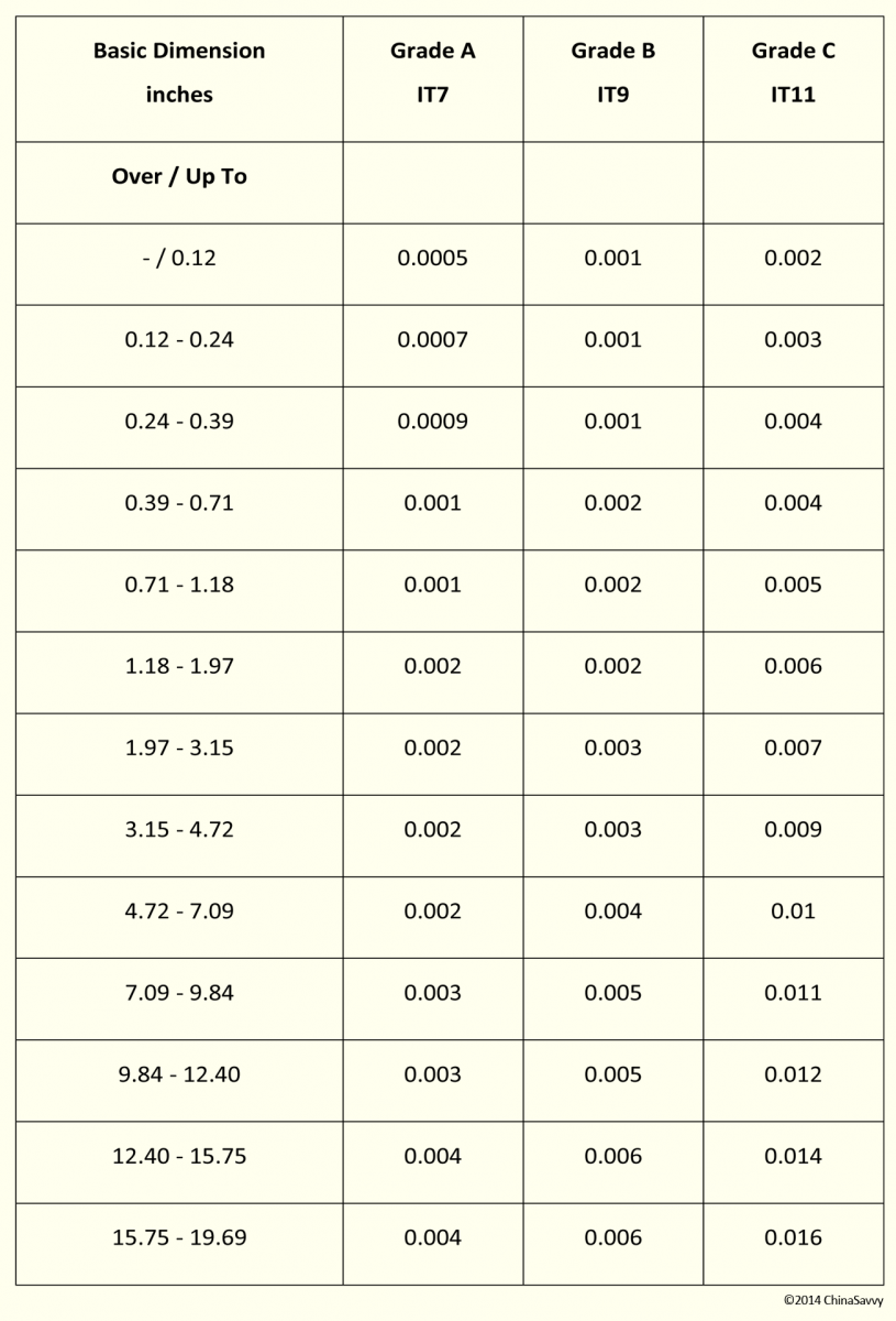

or on the or TABLE 6-1 DESCRIPTION OF PREFERRED FITS (ANSI ) ISO SYMBOL Hole Shaft Basis Basis DESCRIPTION H11/c11 C11/h11 Loose running fit for wide commercial tolerances or allowances on external members.ģ More H9/d9 D9/h9 Free running fit not for use where accuracy is essential, but good for large Clearance Clearance temperature variations, high running speeds, or heavy journal pressures. The CD is now available from ANSI, GO, Inc. NOTE *Complete ISO System of Limits and Fits is now stored a CD KOK ISOTOLTM Computer Tolerancing Software. Tolerance Zones for holes are shown in Fig. Now also available on-line at the site shown below. Select the basic size from Table 4-1 and one of the ten fits from Table 6-1 and read or cut and paste limit dimensions and clearances (interferences) from Tables 6-2 through 6-6 or CD. The hole basis fits have four preferred hole tolerances (H11, H9, H8, and H7) the shaft basis fits have four preferred shaft tolerances (h11, h9, h7, and h6) as shown in Table 6-1.Ģ The above shaft tolerances are now covered in the new ANSI standard. If held to these tolerances, cutting tools, material stock, and gages are generally available throughout the world. Permanent couplings of gears with shafts, flanges.1 Chapter 6 The ISO System of Limits and Fits - Tolerances and Deviations SUMMARY* The ISO System of Limits and Fits is a coordinated System of hole and shaft tolerances for engineering and manufacturing used for cutting tools, material stock, gages, etc.

Assembly using pressing and great forces under different temperatures of the parts. Permanent coupling of gears with shafts, bearing bushings. Assembly using cold pressing only with use of large forces. Assembly of the parts can be carried out using cold pressing. Pressed fits with guaranteed interference. Mounting of fits using pressing and light force.įixed plugs, driven bushings, armatures of electric motors on shafts, gear rims, flushed bolts. H8/p7, H8/m7, H8/n7, H7/m6, H7/n6, M8/h6, N8/h7, N7/h6įixed fits with negligible clearances or small interferences.
#ISO FITS AND TOLERANCES CHART MANUAL#
The parts can be assembled or disassembled without great force using a rubber mallet.ĭemountable fits of hubs of gears and pulleys, manual wheels, clutches, brake disks. Similar fits with small clearances or small interferences. The parts can be assembled or disassembled manually.Įasily dismountable fits of hubs of gears, pulleys and bushings, retaining rings, frequently removed bearing bushings. Tight fits with small clearances or negligible interference. Precise guiding of machines and preparations, exchangeable wheels, roller guides. Mounting by sliding on without use of any great force, after lubrication the parts can be turned and slid by hand. Sliding fits with very small clearances for precise guiding and centring of parts. The parts can easily be slid one into the other and turn.Įasily demountable parts, distance rings, parts of machines fixed to shafts using pins, bolts, rivets or welds. Slipping fits of parts with great tolerances. Parts of machine tools, sliding gears and clutch disks, crankshaft journals, pistons of hydraulic machines, rods sliding in bearings, grinding machine spindles. Without any noticeable clearance after assembly. Running fits with very small clearances for accurate guiding of shafts. General fits of shafts, regulator bearings, machine tool spindles, sliding rods. Running fits with smaller clearances with general requirements for fit accuracy. in agricultural machines, bearings of pumps, fans and piston machines. Running fits with greater clearances without any special requirements for fit accuracy.įits of long shafts, e.g. Multiple fits of shafts of production and piston machines, parts rotating very rarely or only swinging. Running fits with greater clearances without any special requirements for accuracy of guiding shafts. Pivots, latches, fits of parts exposed to corrosive effects, contamination with dust and thermal or mechanical deformations.

Calculate upper and lower limits for shafts and holes (bores).


 0 kommentar(er)
